| Available Bearings | Bearing Selector | Technical Info | New Products | |||
Bearing Geometry Technical Information and Design Factors || Dynaroll
TECHNICAL PAPERS
Inch Precision
Metric Precision
600 Series
6000 Series
6200 Series
6300 Series
6800 Series
6900 Series
R Series
Thrust Bearings
Stainless Steel Thrust Bearings
Thin Section Bearings
Collar Bearings
Flangette Collar Bearings
Specify by Type
Specify by Desired Dimensions
Specify by Cross-Reference
Specify by Known Part Number
Part Numbering System
TECHNICAL PAPERS
DESIGN FACTORS WHEN USING SMALL BEARINGS, PART 1: BEARING GEOMETRY (Page 2)
Common
radial play values are given in the table below:
STANDARD RADIAL PLAY RANGES AND APPLICATIONS
|
|||||||||||||||||||||||||||
| Note: final radial
play after assembly is the important operating condition, therefore,
compensation for interference must be made in the bearing specification.
Note that bearing manufacturers’ radial play values are given as a range. Tighter tolerance of the radial play may be specified, but it will increase the cost of the bearing since a sorting process is used to select specific radial play values. Preload and Axial Play In an application where accurate rotation is
needed, the radial play must be removed from the bearing. Unless
this is done, the races can bounce around relative to each other.
The radial play is normally removed by using a pair of bearings
which are preloaded to remove the play by pressing the races together
axially until the balls are in firm contact with the raceways.
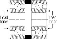
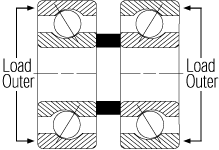
Note that in the examples above, preload
is achieved by pressing the inner races together (or outer races
apart) to give O-type preload or by pressing the outer races together
(or inner races apart) to give X-type preload. The O and X refer
to the shape formed by the contact angle lines in the diagrams.
|
|||||||||||||||||||||||||||


